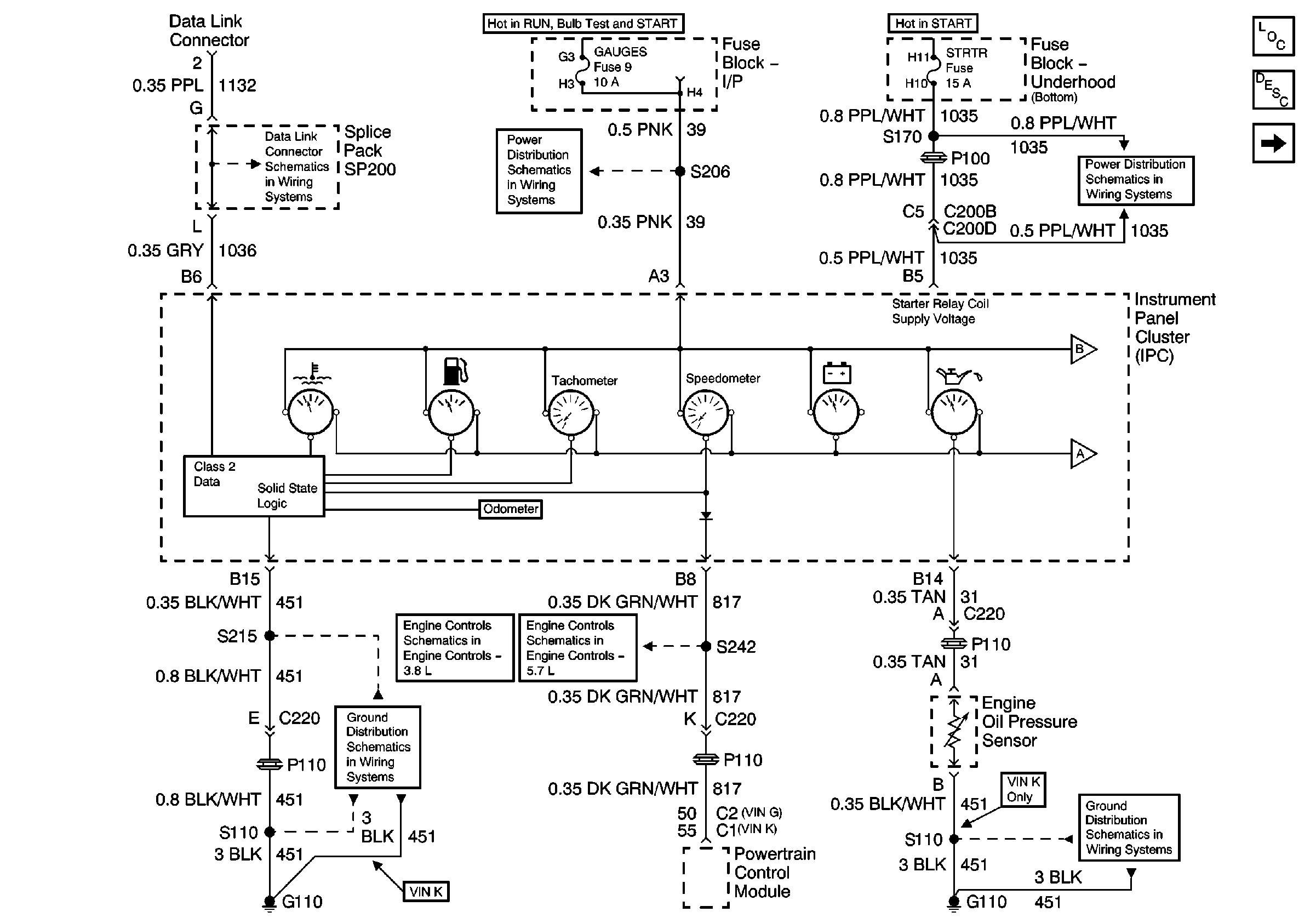
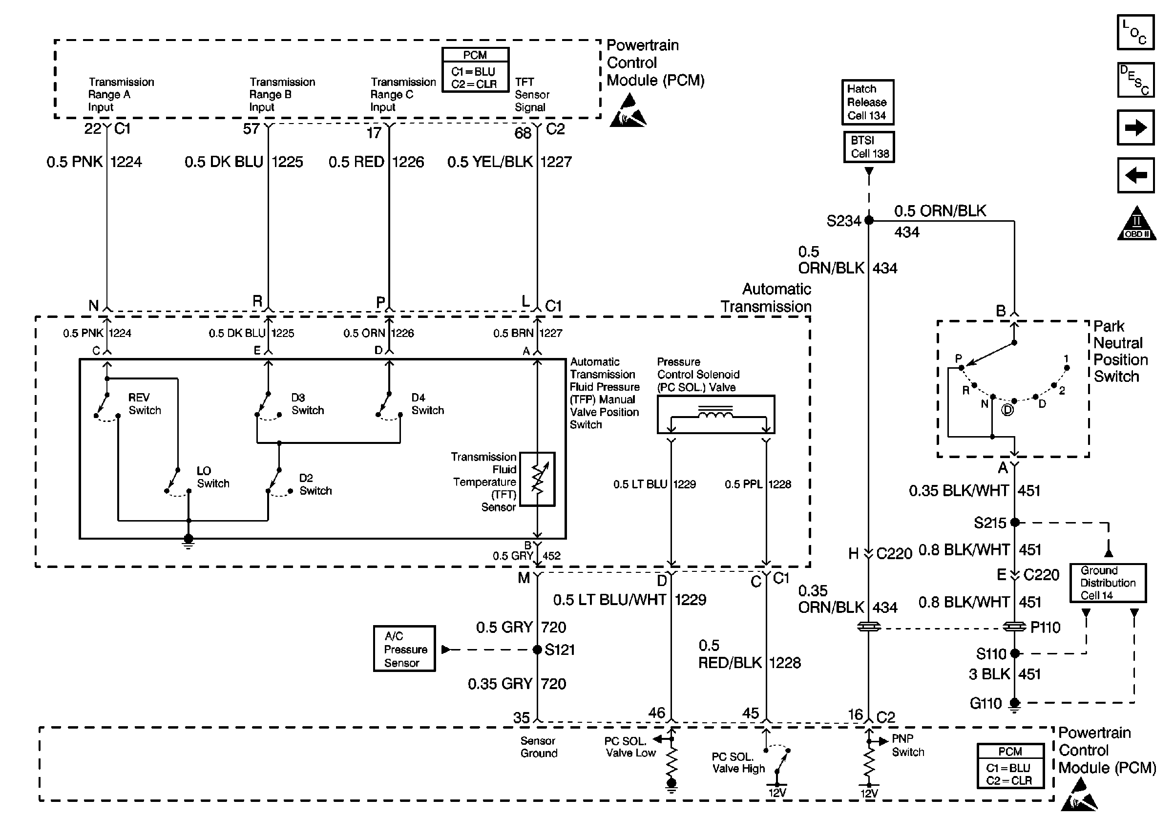
Vss Wiring Diagram
Rj11 Socket Wiring Diagram Australia, How to punch down an RJ11 Telephone Jack, 6.36 MB, 04:38, 387,634, CableSupply.com, 2009-08-05T00:16:07.000000Z, 19, Rj11 Socket Wiring Diagram Australia | Computacion, Redes de computadoras, Computadoras, www.pinterest.com.mx, 728 x 783, jpeg, rj11 wiring rj45 diagram cable ethernet usb jack pinout adapter cat5 female male convert using rs485 cat wires code socket, 20, rj11-socket-wiring-diagram-australia, Anime Arts
It's a little white box behind the glove box. The vss wires to that box. Then sends the signal to the cruise, ecm, and dash. Make sure u have 12 volts goin to that buffer.
If it won't shift, the problem will lie between the sensor to the buffer, or buffer to the ecm. The maf system uses a speed buffer that takes the speed sensor signal and converts it to a signal that the ecm uses. On that basis the vss signal would be split at the buffer ; To the ecm and the speedo which would account for your speedo working without the ecm. Have to check my '87 fsm and check wiring from buffer to dash. Vehicle speed sensor connector wiring harness plug 4l60 lt1 r4 4l60e. 700r4 vss wiring diagram. You will have to use the calibration button that came with your speedo. (this is usually a green wire in gm ls engine harnesses. ) 5) connect the red wire of the gauge cluster wire harness to the red wire of a sn16 pulse signal generator.
Wiring Help - VSS plug details - LS1TECH
Wiring Help - VSS plug details - LS1TECH - Camaro and Firebird Forum Discussion

2-wire and 3-speed sensor/sender - ClubLexus - Lexus Forum Discussion
1992 Camaro 5 Speed Vss Wiring Diagram

VSS Wire - Jeep Wrangler Forum
Solution: Swap with 3 wire VSS - LS1TECH
2005 Hyundai Sonata VSS wire and reverse - Vehicle Specific Wiring - AVIC411.com
06 Honda Odyssey Vss To Pcm Wiring Diagram

VSS wiring question. - GM Performance
Diagnostic Information and Procedures - DTC P0503 Vehicle Speed Sensor (VSS) Circuit
